Microservices bring many benefits to any organization’s software practice. It can be efficiency, speed of changes and improvements, granularity of control over application behavior, solid and stable end-user experience with multiple instances of the service running in parallel, and also global reach with ability to get services closer to the user geographical location and more.

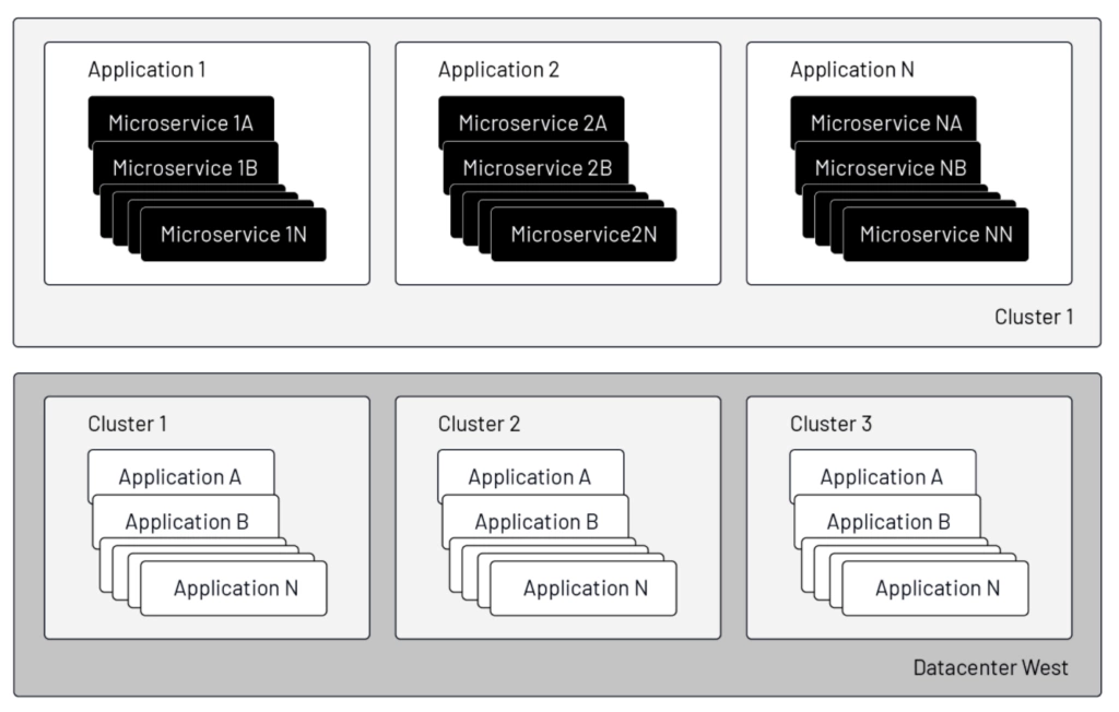
Microservices, of course, do not exist in a vacuum. In most applications, if we zoom out from the individual services themselves, larger structures emerge that must be managed: applications as groups of services; compute clusters as application supersets; data centers hosting these clusters; regions where the clusters are placed; and networks to which and through which clusters are connected. The curious mind will immediately look for operational efficiencies in composing and managing these resources: how to provision the same service in multiple locations, keep traffic as local as possible, yet failover to remote instances in the case of a (planned or unplanned) outage and failback when local service is restored, all with complete transparency to end users.
In this context, let’s examine how Tetrate Service Bridge (TSB) manages such a failover/failback scenario.
Here is our example setup:
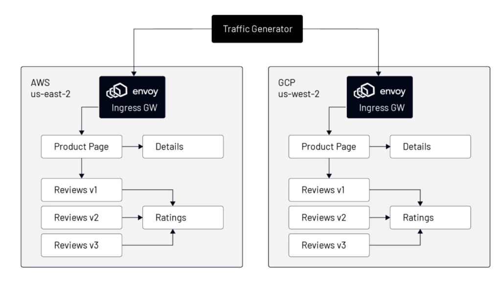
- We will use the Istio demo app, Bookinfo, as our subject.
- We’ll create two Kubernetes clusters: one hosted in AWS, the other hosted in GCP.
- Both clusters will have the exact copy of the multi-service bookinfo app.
- We’ll examine the setting for each cluster and published services.
- Then we will shutdown (scale to 0) all of the instances of a particular service in one cluster and observe that the requests for that service are transparently to the user routed to instances of that service in the other cluster.
The main concept used here is Istio’s “locality load balancing.” The granularity of the failure domain starts at the region level, but can be narrowed in scope to availability zone and further refined with a user-defined sub-zone.
In our example, clusters placed in different clouds and regions is sufficient to demonstrate locality load balancing. Refining the failure domain to availability zone or user-defined sub-zone is functionally equivalent and equally supported in TSB.
Step one: configure clusters in TSB
We will first define two cluster objects as shown in the TSB configuration below. Each cluster will have locality to the region that matches the labels on cluster nodes. Those labels are usually defined by your cloud provider, however region and zone values can also be user specified, even in public cloud deployments. If additional granularity is required, we may add the `istio-locality` label to individual Applications objects with a value in the `regionX.zoneY.subzoneZ` format. If this label is present, Istio’s Pilot agent will configure each Envoy instance with these locality values instead of those from the Kubernetes API.
The AWS cluster configuration is as follows:
The GCP cluster configuration is identical, save for the cluster and region names:
Step two: deploy application instances in each cluster
Next, we deploy the same application in the “bookinfo-backend” namespace. This will be the full application even though the namespace is called ‘backend’. This naming convention comes from the perspective of TSB’s Tier-1 Gateway that will be run outside of our application clusters to load balance inbound traffic to both clusters.
Below is a single ingress manifest that will expose the application home page service––”Bookinfo Productpage”––and the “Bookinfo Details” service––which we will scale to zero (to demonstrate failover) in one of the clusters––in every TSB-managed cluster where “bookinfo-backend” is created.
You will notice multiple TSB-related constructs such as organization, tenant, and workspace. Those are used to map higher-order organization-aware constructs onto Istio-specific configuration. The tenant and workspace constructs provide permissions guardrails between application teams operating in a shared cluster environment so each team can have ownership over its own application resources without stepping on each other’s toes. It’s also possible to give infrastructure admins privileges specific to their area of expertise–– e.g., security admin permissions may be configured to allow, for example, updates to TLS certificates, but deny adjustments to traffic routing rules.

In the manifest, we configure two hostnames (for the “productpage” and “details” services) routing to two backend services. This single definition above will create all necessary objects in both cluster AWS and GCP. After applying the above ingress manifest, Kubernetes will have the following objects defined:
$ kubectl get vs,gw -n bookinfo-backend
NAME                                                                            GATEWAYS                                                 HOSTS                                AGE
virtualservice.networking.istio.io/ingress-bookinfo-916914ed598f92b8-bookinfo   ["bookinfo-backend/ingress-bookinfo-916914ed598f92b8"]   ["demo-1-bookinfo.cx.tetrate.info"]   15d
virtualservice.networking.istio.io/ingress-bookinfo-916914ed598f92b8-details    ["bookinfo-backend/ingress-bookinfo-916914ed598f92b8"]   ["details.cx.tetrate.info"]           15d

NAME                                                            AGE
gateway.networking.istio.io/ingress-bookinfo-916914ed598f92b8   15d
Istio will keep traffic local based on the ServiceEntry definition that TSB has created based on the locality of the service for the cluster. The configuration below contains the important parts of the ServiceEntry record for the AWS cluster in us-east-2:
Step 3: Initiate failover
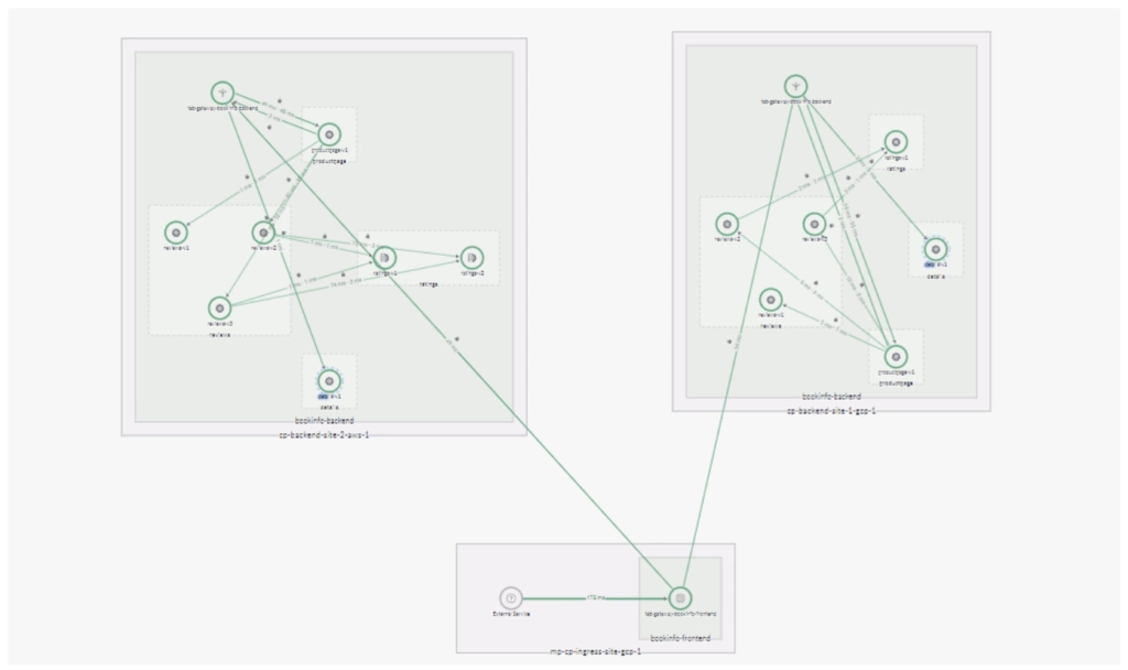
It’s easy to confirm the traffic flow from the TSB web UI:

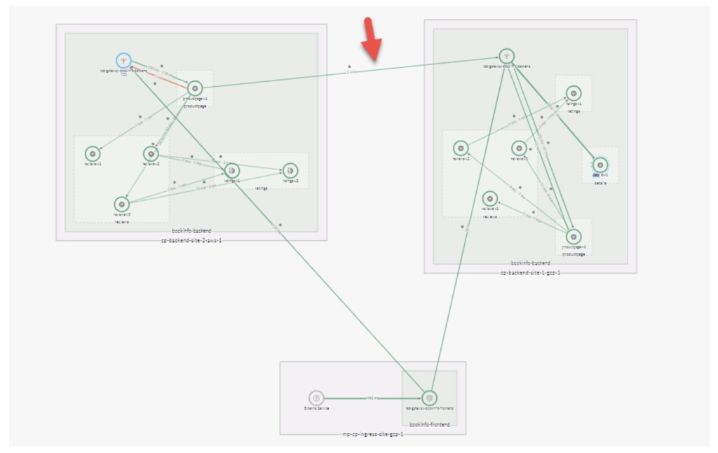
As the map shows, instances of the Productpage service are served by a local instance of the Details service. To initiate a failover scenario we scale the Details deployment in one of the sites to zero replicas.The log below demonstrates how all the traffic initially went to the local service. Then, when the local deployment is scaled to zero, all attempts to reach the service locally fail with 503 URX and traffic is routed to remote sites. The entire failover process happens automatically, with no interruption in service to the end user. The proper page (with a 200 response code) is delivered transparently to the user from the remote location. As part of health check and outlier detection, Envoy periodically attempts to reach the local service and, when the local service recovers, local requests for the service will be routed to the local endpoint again.

To get a visual view of the failover we can see the changes in TSB UI topology view (Figure 4) where the mTLS connection between clusters is established and the ProductPage calls to the Details service leave AWS cluster to be served by the remote Ingress Gateway in GCP.

Conclusion
In this example, we’ve seen how TSB offers a single point of configuration and management for applications replicated in multiple locations. The globally managed service mesh instances in each cluster ensure application resiliency by routingrequests locally when possible and, if the local service is unavailable, transparently routing to the remote cluster. Failover is transparent to the end-user and completely automated. Human interaction with the mesh is not required, however more granular, hands-on control is on tap for infrastructure admins via the centrally managed configuration and observability offered by the enterprise service mesh. The nature of the failover is also clearly presented in the UI, logging, and tracing and can be understood and analyzed using visual tools.